

Views: 0 Author: Site Editor Publish Time: 2026-07-11 Origin: Site


High-volume industrial processing often exceeds the volumetric capacity and cut-point efficiency of a single cyclonic separator. This creates critical bottlenecks in plant throughput. Plant engineers and process managers face a difficult trade-off. They can increase the diameter of a single hydrocyclone, which degrades fine particle separation efficiency. Alternatively, they can manage the complex fluid dynamics of multiple smaller units. A hydrocyclone group engineered for parallel operation resolves this conflict directly. It provides a scalable framework for evaluating manifold designs, specifying cluster configurations, and mitigating operational downtime. By distributing the feed across multiple smaller cyclones, facilities maintain high centrifugal forces required for fine separation while processing massive slurry volumes. This approach eliminates the compromise between throughput and classification sharpness, ensuring downstream processes receive optimal feed sizing.
Maintaining high centrifugal forces is the baseline requirement for fine separation. Processing massive slurry volumes simultaneously complicates this objective. Large diameter cyclones handle high flow rates but fail to generate the g-forces necessary to separate ultra-fine particles. Engineers must design systems that achieve both high volumetric throughput and precise particle classification without sacrificing operational stability. When a plant needs to separate particles at 40 microns, a 30-inch cyclone will simply pass those fines to the underflow or misplace them. The success criteria demand a system that hits the target cut point consistently across varying feed conditions.
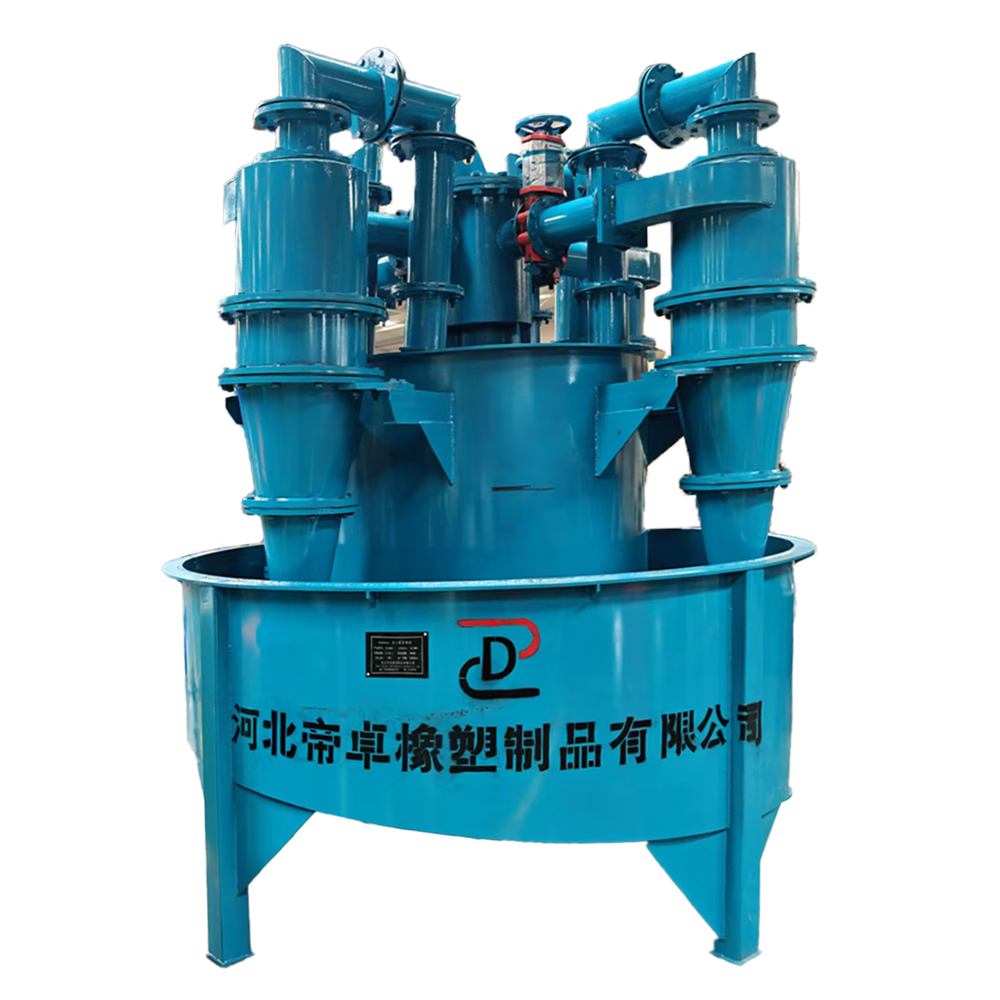
Cyclone diameter shares an inverse relationship with separation efficiency. Smaller diameter cyclones create higher centrifugal forces. These forces pull finer particles toward the outer wall for discharge through the apex. Grouping multiple smaller-diameter units in parallel forms a hydrocyclone cluster. This is the standard engineering solution for high-capacity fine mineral classification. It allows a facility to multiply its flow capacity while retaining the sharp cut points of a small-diameter unit.
| Parameter | Single Large Hydrocyclone | Hydrocyclone Group (Multiple Small Units) |
|---|---|---|
| Volumetric Capacity | High per unit | High total (scalable based on unit count) |
| Cut Size (d50) | Coarse (typically >100 microns) | Fine (can achieve <20 microns) |
| Centrifugal Force | Low to Moderate | Very High |
| Maintenance Downtime | Requires full system shutdown | Zero downtime with isolation valves |
| Footprint | Compact vertical space | Requires larger manifold footprint |
A hydrocyclone group leverages centrifugal force to separate solid phases in aqueous solutions. The separation relies on physical size and relative density differentials. Heavier, coarser particles move toward the cyclone wall and exit as underflow. Lighter, finer particles migrate to the low-pressure center core. They move upward and exit through the vortex finder as overflow. Specific gravity dictates how quickly a particle responds to these centrifugal forces. For example, high specific gravity minerals like gold or galena will report to the underflow much faster than lighter silica particles of the exact same physical diameter.
These systems rely heavily on a continuous, pressurized feed source. High-performance centrifugal pumps typically drive the slurry into the manifold. The pump must maintain a constant pressure drop across all operating units in the cluster. Fluctuations in feed pressure alter the internal fluid dynamics. This shifts the cut point and degrades separation efficiency. Proper pump sizing ensures consistent centrifugal force generation. If the pump surges, the air core inside each cyclone collapses, leading to immediate misclassification and potential plugging of the apex.
The manifold is the structural and functional backbone of the cluster. It dictates how well the individual cyclones perform together.
Hydrocyclone groups play a crucial role in ball mill and SAG mill circuits. They classify the mill discharge, sending coarse particles back for regrinding. Fine particles advance to the next processing stage. Precise mineral classification prevents overgrinding. This reduces unnecessary energy consumption and optimizes downstream recovery processes. Sharp cut points directly improve the overall efficiency of the grinding circuit. When a cluster operates efficiently, the circulating load drops, allowing the mill to accept more fresh feed.
Clusters excel in removing ultra-fine clays or slimes prior to flotation or leaching. Slimes interfere with chemical reagents and reduce recovery rates. Degritting operations separate highly abrasive heavies and grit from process water. This protects downstream equipment from accelerated wear. Maximizing fines recovery in tailings management carries a significant economic impact. It captures valuable minerals that would otherwise be lost to waste. Specific applications include:
Hydrocyclone groups are heavily utilized in washing and sizing sand. They dewater construction aggregates and industrial minerals. These operations must meet rigorous industry grading standards. The clusters remove unwanted clay and silt from the final product. They ensure the sand meets strict specifications for concrete or asphalt production. Consistent classification yields a higher quality, more marketable aggregate product. Frac sand production, for instance, relies entirely on tight cluster classification to meet API standards.
Facilities utilize hydrocyclone groups to thicken slurry separation streams. This densification occurs prior to filtration, centrifugation, or pumping. Removing excess water reduces the volumetric load on downstream dewatering equipment. It lowers capital costs by allowing the use of smaller filters or centrifuges. Thickened underflow is also easier to transport via pipeline. By pulling water out through the overflow, the underflow density can be pushed to 60-70% solids by weight.
Calculating the total required volumetric flow rate determines the baseline number of operating cyclones. Engineers must align the cyclone diameter with the required particle separation threshold. Vortex finder and apex dimensions are then fine-tuned to hit specific cut size (d50) targets. Matching the cluster's operating pressure requirements with the upstream centrifugal pump is vital. The pump curve must intersect the system resistance curve at the optimal operating point. If the pump cannot deliver the required head pressure, the cyclones will not generate sufficient centrifugal force.
The physical layout of the cluster impacts both performance and maintenance access.
| Configuration Type | Primary Advantages | Primary Disadvantages |
|---|---|---|
| Radial Distributor | Symmetrical feed distribution, uniform wear rates, identical pressure to all units. | Requires a large circular footprint, complex piping layout. |
| In-Line Distributor | Compact footprint, fits easily into existing rectangular plant layouts. | High risk of pressure drops, uneven solids distribution at the end of the header. |
A well-engineered hydrocyclone group accommodates fluctuations in plant feed rates. Operators can bring individual units online or offline as needed. This maintains the optimal pressure drop across the active cyclones. A high turndown ratio provides operational flexibility. It prevents the system from operating outside its designed efficiency range during low-flow conditions. If plant feed drops by 30%, operators simply close the isolation valves on a few cyclones to maintain the required 15 PSI pressure drop on the remaining active units.
Preferential flow causes coarse particles to overload specific cyclones. This leads to a condition known as "roping," where the underflow discharges as a thick, rope-like stream. Roping indicates poor separation and lost fines to the underflow. Strict adherence to distributor design tolerances mitigates this risk. Routine pressure monitoring across the cluster identifies imbalances before they impact product quality. Installing pressure gauges on the feed header of every individual cyclone provides immediate visual feedback to the operators.
Highly abrasive ore processing rapidly degrades internal cyclone geometries. Wear alters the vortex finder and apex diameters, shifting the cut point. Selecting the correct liner material is critical. Molded polyurethane suits fine to moderate wear applications. Alumina ceramic withstands highly abrasive slurries. Natural rubber absorbs coarse impact in primary grinding circuits. Silicon carbide is often specified for the apex, as it experiences the highest velocity and abrasion rates in the entire assembly.
Unplanned plant downtime often stems from difficult-to-reach apexes or jammed isolation valves. Operators must be able to swap wear parts quickly. Specifying clusters with clear maintenance access platforms reduces downtime. Reliable, slurry-rated knife gate valves ensure complete isolation. Proper access transforms a major maintenance shutdown into a routine, mid-shift task. Walkways should allow a technician to safely unbolt a spigot housing without requiring scaffolding or specialized lifting equipment.
A: The terms are used interchangeably in the industry. Both describe multiple hydrocyclones operating in parallel from a single feed source and manifold system to increase total volumetric capacity.
A: A group can range from 2 units to over 30 individual cyclones. The exact number depends entirely on the selected cyclone diameter and the total volumetric flow requirements of the processing plant.
A: Roping occurs when the underflow is overloaded due to excessive solids concentration or severe apex wear. It disrupts the internal air core, causing coarse material to discharge in a thick stream and degrading separation efficiency.
A: Feed pressure dictates the pressure drop across the cyclone. Higher pressure increases centrifugal force, which drives finer particles to the underflow and decreases the overall cut size.
A: Yes, provided the manifold is engineered with individual feed isolation valves. Operators can close the valve, isolate the unit, and replace wear parts while the rest of the cluster continues operating.
A: Smaller diameters generate the higher g-forces required for finer particle classification. Grouping them allows the plant to process high volumes while maintaining these precise, fine cut points.


