

Views: 0 Author: Site Editor Publish Time: 2026-09-06 Origin: Site


In high-throughput mineral processing and mill concentrator applications, premature equipment wear and inefficient particle separation directly erode plant efficiency through unplanned downtime and lost recovery. High-wear applications demand a delicate balance. Operators must manage highly abrasive slurries while maintaining precise cut points and handling massive volumetric throughputs that a single unit cannot process efficiently. Selecting the optimal classification equipment requires moving beyond basic capacity charts. You need a technical evaluation framework for sizing, material specification, and configuration to ensure reliable classification. This guide breaks down the engineering principles behind clustering smaller cyclones to achieve high volumetric throughput without sacrificing the centrifugal force required for fine particle separation. We will cover material selection, manifold hydraulics, and maintenance strategies to keep your circuit running continuously.
Throughput vs. Precision: Replacing one large cyclone with a hydrocyclone cluster of smaller units (e.g., 40–400mm) achieves finer cut points (down to 40 microns) while maintaining required plant capacity.
Material Specification is Critical: High-wear environments require strategic material selection, often utilizing hybrid configurations like polyurethane bodies with silicon carbide (SiC) or advanced ceramic apexes.
Redundancy Drives Uptime: Properly specifying the ratio of operating to standby cyclones within the manifold ensures continuous operation during routine apex or vortex finder replacements.
System-Level Evaluation: A successful slurry classification system must be evaluated on manifold hydraulics, feed distribution symmetry, and integration with upstream pump performance.
Establishing baseline operational parameters forms the foundation of any successful classification circuit. You must first document the exact slurry rheology entering the system. Specific gravity dictates how individual particles behave under intense centrifugal force. Solids concentration by weight and volume heavily influences fluid viscosity. Particle size distribution (PSD) provides the baseline metric for separation efficiency. You must define the target cut point (d50) carefully. Establish a strict acceptable tolerance for misplaced fines in the underflow. Map the specific application context thoroughly. Tailor these parameters differently for primary mill concentrator applications versus secondary grinding or tailings management.
For instance, a primary grinding circuit handling coarse, highly abrasive quartz requires a completely different setup than a regrind circuit processing softer sulfides. You have to measure the feed pressure dynamically. Static pressure readings often mask underlying pump surging. We always recommend installing inline pressure transmitters right at the manifold inlet. This gives operators real-time data to adjust pump speeds and maintain a stable air core inside the units.
Identifying primary wear mechanisms prevents premature equipment failure. Highly abrasive slurries destroy standard materials rapidly. Analyze sliding abrasion in the lower cone and apex. These zones experience the highest particle velocities and friction. Evaluate impact wear at the feed inlet and vortex finder. Slurry enters the inlet tangentially at high pressure, causing severe localized gouging. Assess chemical corrosion risks if processing acidic or reactive slurries. Certain ores release compounds that degrade standard elastomers over time.
In many gold and copper concentrators, the combination of sharp particle edges and high velocity creates a scouring effect. This scouring strips away protective oxide layers on metal components and shreds standard rubber linings. You must inspect the involute feed head regularly. If you see grooving or channeling in the rubber, the slurry is bypassing the intended flow path. This disrupts the internal fluid dynamics and ruins your separation efficiency.
Setting practical maintenance benchmarks ensures long-term operational stability. Define acceptable maintenance intervals based on plant shutdown schedules. Decide whether your operation requires weeks versus months for routine spigot replacement. Calculate the impact of unexpected downtime on overall plant throughput. Use these operational metrics to justify the specification of premium wear materials. A well-planned maintenance schedule prevents catastrophic failures and keeps the classification circuit running smoothly.
Large single cyclones exceeding 500mm in diameter are strictly limited to coarser separations. They cannot effectively manage fine cuts at high volumetric flow rates. The physics of centrifugal force dictate this limitation. Centrifugal force increases as the radius of the cyclone decreases. Understand the 40-micron threshold. For fine particle separation at 40 microns, a large 30-inch cyclone simply lacks the necessary internal force. It will pass those fines to the underflow or misplace them entirely. This physical limitation necessitates a cluster approach for fine classification.
When you try to force a fine cut in a massive cyclone by jacking up the feed pressure, you only accelerate wear. The pump works harder, the inlet velocity spikes, and the internal linings get shredded. The cut point barely shifts. You end up with a coarse overflow and a massive circulating load that chokes the ball mill. Operators often make this mistake when trying to push plant capacity beyond original design limits.
Clustering smaller cyclones achieves high volumetric throughput without sacrificing centrifugal force. A hydrocyclone cluster divides the massive total feed into manageable streams. Each small cyclone applies intense centrifugal force to its portion of the slurry. This operational logic guarantees precise fine particle separation. Evaluate the footprint and structural support requirements carefully. Radial configurations distribute feed symmetrically but require substantial vertical clearance. Linear configurations fit tighter spaces but demand complex manifold engineering to ensure equal feed distribution.
You must account for the dynamic load of the cluster when full of slurry. A manifold loaded with high-density pulp weighs significantly more than empty steel. Structural steel supports must dampen vibrations from the feed pumps. If the platform shakes, it stresses the flanged connections and leads to leaks. We always specify heavy-duty vibration isolation pads between the cluster frame and the plant decking to prevent structural fatigue.
Scalability and turndown ratios provide operational flexibility. Plant feed rates fluctuate based on upstream milling conditions. Use individual isolation valves on each cyclone within the cluster. These valves allow operators to bring units online or offline dynamically. You can manage fluctuating plant feed rates without losing optimal inlet pressure. Maintaining steady pressure ensures the cut point remains stable despite varying volumetric loads.
Pneumatic pinch valves or heavy-duty knife gate valves work best for isolation. Manual valves get stuck if not cycled regularly. We prefer automated pinch valves tied to the plant control system. When the feed flow drops, the system automatically closes one valve to maintain the target pressure across the remaining active units. This automation prevents the entire cluster from losing pressure during a feed slump.
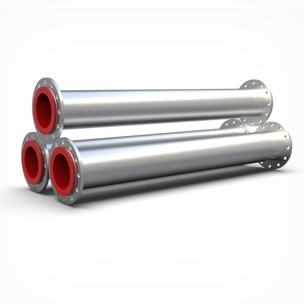
Polyurethane and natural rubber serve as excellent elastomers for moderate wear zones. Use them in upper cylinder sections where impact angles are shallow. These elastomers also excel in applications requiring strong corrosion resistance. Polyurethane absorbs impact energy effectively. However, you must evaluate the replacement frequency against operational demands. Elastomers degrade quickly when exposed to sharp, high-velocity sliding abrasion.
Selecting the right durometer for polyurethane linings makes a massive difference. Softer urethanes handle direct impact better because they rebound. Harder urethanes resist sliding abrasion but can chunk out if hit by large tramp metal. You have to match the polymer blend to the specific ore characteristics. Natural rubber remains the standard for fine, rounded particles, but it fails rapidly if the slurry contains hydrocarbons or flotation reagents.
Advanced ceramics and silicon carbide (SiC) dominate high-velocity, extreme-abrasion zones. Focus these premium materials on the lower cone, spigot, apex, and vortex finder. Silicon carbide offers exceptional hardness. Assess the brittleness risk carefully. Ceramics can fracture under heavy mechanical impact. However, they provide an exponential increase in wear life compared to standard elastomers when handling sliding abrasion.
Never hit a ceramic-lined component with a steel hammer during installation. We see this mistake constantly in the field. Mechanics try to tap a stubborn apex into place and crack the SiC liner. Once cracked, the high-pressure slurry will wash out the backing material in hours. Always use rubber mallets and ensure mating surfaces are perfectly clean before bolting them together.
Hybrid construction strategies offer the best balance of durability and practicality. Specify composite systems for high-wear applications. Combine heavy-duty steel housings with rubber-lined upper sections. Integrate ceramic lower cones and silicon carbide apexes. This hybrid approach optimizes durability exactly where it is needed most. It protects the structural integrity of the unit while extending the lifespan of critical wear components.
Manifold and distributor materials require equal attention. The central feed distributor handles the entire volumetric load before it splits. Evaluate rubber-lined steel against specialized hardened alloys. Protect the central feed distributor and overflow launders against strong corrosion and impact wear. A well-designed cyclone separation system ensures the manifold outlasts the individual cyclone wear parts.
The overflow launder often gets neglected during the design phase. If the launder lacks sufficient slope or uses inferior lining, coarse particles that occasionally bypass the vortex finder will settle and cause rapid localized wear. We line launders with high-alumina ceramic tiles in extreme cases. Ensure the launder has adequate venting to prevent vapor locks and surging, which can back up into the overflow pipes and disrupt the air core.
Determining the optimal cyclone diameter requires matching the physical dimensions to the target cut point. Select 250mm units for specific mid-range cuts. Choose 100mm units for ultra-fine classification. Recognize that configuration flexibility exists. You often face multiple viable engineering choices. Evaluate the trade-offs between utilizing many ultra-small units versus fewer medium-sized units. Smaller units provide finer cuts but require more complex manifolding and more isolation valves.
When you drop down to 100mm units, the apex diameter becomes very small, sometimes less than 20mm. This introduces a severe risk of plugging if your trash screen fails. You must weigh the benefit of an ultra-fine cut against the maintenance headache of constantly clearing plugged spigots. Sometimes, stepping up to a 150mm unit and accepting a slightly coarser cut yields better overall plant stability.
Calculating the number of units involves balancing total flow rate against optimal pressure drop. Determine the active units required to process the maximum volumetric load. Specify 15 to 25 percent standby capacity. This translates to one or three extra units depending on the total cluster size. Standby capacity allows operators to perform on-the-fly maintenance. You can isolate a worn unit, swap the apex, and return it to service without halting the entire grinding circuit.
Operating pressure dictates the centrifugal force. If you design the cluster for a 100 kPa pressure drop but the pump can only deliver 70 kPa, the separation will fail. You must calculate the total dynamic head of the entire circuit, including the vertical lift to the manifold and the friction losses in the feed pipe. Always size the feed pump to handle the maximum anticipated pressure drop as the cyclone linings wear and internal dimensions expand.
Feed distributor and manifold hydraulics dictate overall system efficiency. Evaluate radial distributor designs rigorously. The manifold must ensure equal pressure and symmetrical solids distribution to every single cyclone. Avoid localized starvation or overloading within the mineral processing cyclone group. If one cyclone receives more feed than the others, it will wear out prematurely and disrupt the overall cut point.
In a radial manifold, the slurry enters a central chamber and flows outward equally to all units. This is the gold standard for symmetry. Linear manifolds, where cyclones branch off a straight pipe, almost always suffer from uneven distribution. The units at the far end of the header receive lower pressure and coarser feed. If plant layout forces you to use a linear manifold, you must step down the header pipe diameter progressively to maintain velocity and pressure.
Cyclone Diameter (mm) | Typical Cut Point (d50 in microns) | Capacity Range per Unit (m³/h) | Best Application Use Case |
|---|---|---|---|
100 - 150 | 10 - 40 | 5 - 25 | Ultra-fine classification, tailings management |
250 - 350 | 40 - 80 | 40 - 120 | Secondary grinding, fine mineral recovery |
400 - 500 | 80 - 150 | 150 - 300 | Primary mill concentrator circuits |
600+ | 150 - 300+ | 400 - 800+ | Coarse separation, high-volume dewatering |
Maintenance accessibility defines the long-term viability of the installation. Evaluate the physical design of the cluster carefully. Ensure isolation valves are easily accessible from the maintenance platform. A single apex must be swapped safely while the rest of the cluster operates at full pressure. Develop proactive maintenance strategies. Rotate high-wear components across the cluster. Cyclones positioned near the main feed inlet sometimes experience slightly higher wear. Rotating parts extends overall system life.
Platform design dictates maintenance speed. Mechanics need enough clearance to swing wrenches and use lifting hoists for heavier lower cones. If the platform is cramped, maintenance takes twice as long, and safety risks multiply. We recommend specifying a minimum of one meter of clearance around the entire perimeter of the cluster. Include dedicated lifting davits above the manifold for handling heavy isolation valves and feed headers.
Assess the manufacturer supply chain for proprietary wear parts. High-wear applications consume apexes and vortex finders regularly. You need guaranteed access to exact replacement parts. Delays in parts delivery force operators to run worn cyclones, which destroys separation efficiency and damages downstream equipment.
Keep a dedicated consignment stock of critical wear parts on-site. Do not rely on just-in-time shipping for silicon carbide apexes. If a tramp metal event shatters three apexes simultaneously, you need replacements immediately. Standardize the cyclone sizes across your plant wherever possible to minimize the variety of spare parts you must hold in inventory.
Prioritize vendor-supplied computational fluid dynamics (CFD) modeling during the design phase. CFD modeling predicts wear patterns accurately. It validates fluid dynamics inside the manifold before fabrication begins. Vendors who provide transparent CFD data demonstrate a deep understanding of slurry rheology. This engineering support ensures the final manifold design distributes feed symmetrically and minimizes turbulent wear zones.
Look for CFD reports that specifically model particle trajectories, not just fluid flow. Slurry does not behave like clean water. The high-density particles will segregate if the manifold design creates dead zones or excessive swirl before the slurry even enters the cyclones. A proper CFD model will highlight these problem areas so the vendor can adjust the internal baffling of the distributor before cutting any steel.
Misplaced fines and underflow crowding present significant operational risks. This condition, known as roping, occurs when the underflow discharge loses its spray pattern and exits as a thick rope. Roping forces coarse particles into the overflow and misplaced fines into the underflow. Mitigate this through proper apex sizing. Implement automated pressure monitoring to detect roping early. A reliable slurry classification system uses sensors to alert operators before roping impacts downstream recovery.
Operators should perform visual checks of the underflow discharge every shift. A healthy discharge forms a wide, hollow umbrella shape. If the umbrella starts to collapse and narrow, the cyclone is approaching a roping condition. You can often correct this temporarily by opening an additional standby cyclone to reduce the volumetric load on the active units, giving the apexes room to breathe.
Feed surges and pressure fluctuations destabilize the cut point. Cyclones require steady inlet pressure to maintain the internal air core. Mitigate pressure drops by integrating variable frequency drives (VFDs) on the upstream feed pumps. Utilize the automated isolation valves on the cluster. If plant feed drops, the VFD slows the pump, and the control system isolates one or two cyclones. This maintains steady-state pressure across the remaining active units.
Pump surging usually originates in the pump box or sump. If the sump level drops too low, the pump ingests air. This air travels up the feed line, enters the manifold, and violently collapses the air cores inside the cyclones. You will hear a distinct hammering sound when this happens. Maintain strict sump level control loops to prevent air entrainment and protect the internal linings from cavitation damage.
Uneven wear across the cluster indicates poor manifold design. If slurry favors one side of the manifold, those specific cyclones will suffer accelerated abrasion. Mitigate this by specifying a geometrically symmetrical feed manifold. Radial manifolds generally provide better symmetry than linear manifolds. Prevent preferential flow by ensuring the feed pipe enters the distributor perfectly centered and vertical.
The final vertical run of pipe entering the bottom of a radial distributor must be straight for at least five pipe diameters. If you place an elbow immediately before the distributor inlet, the centrifugal force from the elbow will push all the coarse solids to one side of the pipe. This segregated feed then enters the distributor, overloading half the cyclones with coarse material while starving the other half.
Audit your current classification circuit by measuring the specific gravity, particle size distribution, and volumetric flow rate of your feed slurry.
Inspect your existing cyclone underflow discharges visually to identify any units exhibiting roping or collapsed umbrella patterns.
Request technical proposals from manufacturers that include computational fluid dynamics (CFD) modeling specific to your slurry rheology.
Specify hybrid material constructions in your procurement documents, mandating silicon carbide for the apex and lower cone, paired with polyurethane upper bodies.
Design your maintenance platform with a minimum of one meter of clearance and integrate dedicated lifting davits to facilitate safe, on-the-fly apex replacements.
A: A cluster utilizes multiple smaller cyclones to process high volumes of slurry while maintaining the high centrifugal forces necessary for fine particle separation. A single large cyclone cannot generate the internal forces required to achieve these fine cut points at massive scales.
A: Selection depends heavily on particle size. For fine cuts around 40 microns, a large unit lacks the necessary centrifugal force. It will simply pass those fines to the underflow or misplace them entirely. A cluster of smaller units generates the intense force needed to classify them accurately.
A: Material selection depends on the abrasion level and impact velocity. Polyurethane or natural rubber works well for moderate wear and corrosion in the upper sections. Advanced ceramics or Silicon Carbide (SiC) are strictly required for high-wear zones like the apex and lower cone to prevent rapid degradation.
A: Premature wear is typically caused by highly abrasive sliding particles, excessive inlet pressure, or uneven feed distribution in the manifold. Specifying an elastomer in a high-velocity zone that requires ceramic lining or allowing tramp metal to bypass the trash screen also accelerates component failure.
A: Smaller diameter cyclones generate higher centrifugal forces, resulting in finer cut points. For example, 100mm units excel at ultra-fine classification. Larger cyclones handle higher capacities but yield coarser separations because the centrifugal force decreases as the internal radius of the unit increases.
A: Industry standards dictate including 15 to 25 percent standby capacity. This typically translates to one to three extra units depending on the total cluster size. Standby units allow operators to perform routine maintenance and wear part replacements without shutting down the entire grinding circuit.
A: While highly dependent on slurry abrasiveness and operating pressure, a silicon carbide apex typically lasts 6 to 12 months. It offers significantly longer wear life compared to standard polyurethane or rubber alternatives, drastically reducing maintenance frequency and downtime in extreme sliding abrasion conditions.


