

Views: 0 Author: Site Editor Publish Time: 2026-09-08 Origin: Site


Premature pipeline failure in high-abrasion environments drives massive operational downtime across industrial sectors. Generic material selection often leads to unplanned maintenance, environmental hazards, and inflated repair budgets. Specifying piping for harsh conditions requires exact precision and a deep understanding of fluid dynamics. Ordering errors cause flow restrictions, severe delamination, and catastrophic blowouts. Common mistakes include ignoring the finished Internal Diameter (ID) after lining, choosing the wrong durometer, or overlooking maximum temperature limits. Domestic supply chain lead times also play a major role in project execution and facility uptime.
We present a structured evaluation framework for specifying polyurethane lined pipe. This guide moves from baseline dimensional requirements and pressure ratings to chemical compatibility. We also cover fitting specifications, bonding methodologies, and quality assurance standards necessary for a successful procurement cycle. Engineers and procurement teams can use this framework to eliminate guesswork and engineer systems built for maximum longevity.
Finished ID Dictates Flow: Polyurethane linings (ranging from thin-film 20 mils to 2-inch heavy-duty layers) alter the internal diameter; specifications must account for the finished ID to maintain required flow rates.
Directional Changes Require Extra Attention: Fittings (elbows, tees, reducers) experience the highest wear rates; specifying thicker linings or specialized durometers in these zones is critical for system longevity.
Bonding Methodology is Critical: Chemical bonding of the liner to the steel substrate prevents delamination under vacuum or high-velocity conditions, offering superior longevity compared to mechanical friction fits.
Application-Specific Durometer: Hardness must be matched to the media; softer urethanes often perform better against sliding abrasion, while harder urethanes resist impact.
Thermal and Chemical Limits: Standard polyurethane degrades in high-heat or high-hydrolysis environments; exact operating temperatures and fluid compositions must be verified prior to ordering.
Define operational thresholds clearly before initiating a procurement cycle. Bare steel, rubber, or ceramic-lined pipes often fail early in severe conditions, causing unacceptable facility disruptions. Establish baseline success criteria based on historical wear data. Look for extended mean time between failures (MTBF) and significantly reduced maintenance intervals. Facility managers must track how often standard pipes require rotation or replacement to justify upgrading materials. Understanding the exact failure modes of previous piping systems allows engineers to specify a liner that directly addresses those weaknesses.
Industrial facilities pumping silica sand, copper tailings, or heavy mineral sands face extreme sliding abrasion. In these environments, standard carbon steel pipe walls thin out rapidly. Plant operators frequently resort to rotating the pipe 90 degrees every few months to distribute the wear evenly. This manual rotation requires heavy equipment, scaffolding, and significant labor hours. Upgrading to a specialized lining eliminates this constant maintenance requirement, allowing the maintenance crew to focus on critical rotating equipment rather than static piping networks.
Material Type | Sliding Abrasion Resistance | Impact Resistance | Hydrocarbon Compatibility | Weight Impact |
|---|---|---|---|---|
Bare Carbon Steel | Low | High | Excellent | Baseline |
Natural Rubber Lined | Moderate | Excellent | Poor (Swells) | Moderate Increase |
Ceramic Lined | Excellent | Low (Brittle) | Excellent | High Increase |
Polyurethane Lined | Excellent | Moderate to High | Excellent | Low Increase |
Contrast polyurethane against traditional rubber linings and unlined steel to understand its mechanical advantages. Polyurethane offers a unique specific gravity and exceptional abrasion resistance that outperforms traditional materials in sliding wear applications. It tackles the destructive corrosion-abrasion cycle effectively. In bare steel pipes, acidic or wet media causes corrosion, softening the internal wall. The abrasive media immediately strips away that oxidized layer, exposing fresh steel to further corrosion. Polyurethane halts this cycle entirely because it remains inert to many mild chemicals and physically blocks the media from touching the steel.
This dual resistance protects the internal structure from rapid degradation. Polyurethane also boasts high compatibility with oil, grease, and hydrocarbons. Natural rubber compounds absorb oils, causing them to swell, soften, and eventually tear away from the pipe wall. Polyurethane maintains its structural integrity and durometer even when exposed to these aggressive fluids. These properties make it uniquely suited for demanding industrial environments, mineral processing facilities, and heavy-duty mining applications where tramp oils frequently mix with the slurry.
Understand the critical difference between nominal pipe size and finished ID. A lining thickness ranging from 1/4" to 2" significantly impacts internal volume and fluid velocity. For example, applying a 1-inch liner to a 10-inch nominal pipe reduces the open area drastically. Failing to account for this thickness restricts flow, increases fluid velocity, and spikes system pressure. Higher fluid velocity exponentially increases the wear rate on the liner itself, defeating the purpose of the upgrade.
Standard manufacturing capabilities typically cover 4" to 60" IDs, allowing for massive industrial scale implementations. You must specify exact internal dimensions for an abrasion resistant slurry pipe network. Proper sizing prevents flow bottlenecks at transition points. Engineers must calculate the required flow rate first, and then size the outer steel shell large enough to accommodate both the required internal open area and the necessary urethane thickness.
Nominal Pipe Size (NPS) | Steel Wall Thickness (Schedule 40) | Liner Thickness | Finished Internal Diameter (ID) | Cross-Sectional Area Loss |
|---|---|---|---|---|
8 inch | 0.322 inch | 0.50 inch (1/2") | 6.98 inch | ~23% |
10 inch | 0.365 inch | 0.75 inch (3/4") | 8.52 inch | ~28% |
12 inch | 0.406 inch | 1.00 inch (1") | 9.94 inch | ~31% |
The table above illustrates how aggressively a thick liner reduces the available flow area. When replacing an unlined 10-inch pipe with a lined 10-inch pipe, the pump must push the same volume of fluid through a much smaller hole. This requires more pump energy and increases the friction head loss across the entire piping system. Always upsize the nominal steel pipe if you need to maintain the exact original internal diameter.
Thickness requirements vary heavily based on the application and the abrasiveness of the conveyed material. Light industrial or septic environments might only need a 20 mils minimum dry film thickness to prevent mild corrosion. Aggressive mining slurries demand heavy-wall linings, often exceeding one inch in thickness, to withstand constant bombardment from sharp ore. Analyze the trade-off between liner thickness, pipe weight, and installation logistics. Thicker liners add substantial weight and reduce internal volume but maximize the operational lifespan of the spool.
Understand the Shore A and Shore D durometer scales to select the correct material hardness. Specify hardness based on the particle size, shape, and velocity of the conveyed media. Matching the durometer to the specific wear mechanics of the slurry is mandatory for optimizing pipe performance.
60 to 75 Shore A: Extremely soft and resilient. Best suited for fine, round particles like silica sand or fly ash. The soft surface allows particles to bounce off without cutting the material.
80 to 90 Shore A: The industry standard for general slurry applications. Offers a balanced mix of tear resistance and sliding abrasion resistance. Ideal for crushed ore, coal wash plants, and concrete pumping.
95 Shore A to 60 Shore D: Harder formulations designed for larger, jagged particles. Used when the media contains sharp rocks that would gouge or slice a softer urethane.
70+ Shore D: Extremely hard, rigid urethane. Used in high-impact zones where heavy rocks drop directly onto the surface, acting more like a plastic or ceramic than a rubber.
Standard spool length limitations typically max out at 20 to 25 feet. Centrifugal casting processes dictate these manufacturing constraints. During manufacturing, the steel pipe spins on high-speed rollers while a lance injects liquid urethane. Centrifugal force pushes the liquid against the steel wall, creating a perfectly concentric liner. Ensuring a uniform liner thickness over distances greater than 25 feet becomes technically unfeasible due to the curing time of the liquid polymer.
You must specify lined fittings, including elbows, wyes, reducers, and tees, to match the straight spools perfectly. Directional changes suffer the most turbulent wear and require robust protection. When fluid hits an elbow, centrifugal force pushes the abrasive particles against the outer radius (extrados) of the bend. Engineers frequently specify a thicker liner on this outer radius to compensate for the concentrated abrasion. Manufacturers achieve this by offsetting the internal core mold during the pouring process.
Define the requirements for the outer steel shell with precision. Carbon steel grades like ASTM A53 or A106, along with spiral welded steel pipe, provide the necessary structural integrity. Specify the base material carefully for low-pressure gravity-fed systems versus a high-pressure mining lined pipeline network. The steel shell handles the structural load, spanning distances between pipe supports, and contains the internal pressure. The internal urethane handles the severe wear, meaning the steel wall thickness can sometimes be reduced compared to unlined systems. Always verify that the chosen steel grade meets the pressure ratings required by site safety standards.
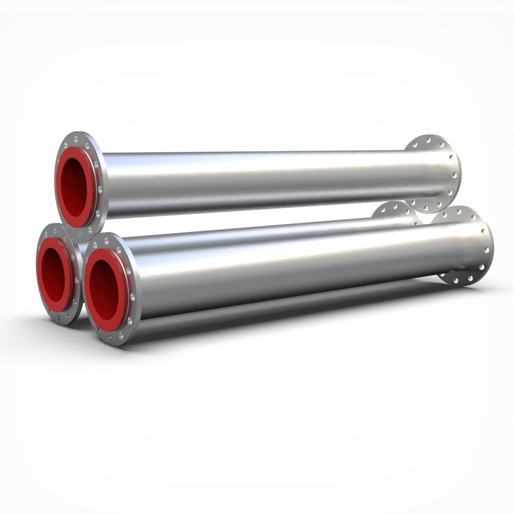
Engineering requirements for end connections demand careful attention to prevent leaks and premature wear at the joints. Common options include fixed flanges, floating (lap joint) flanges, and grooved ends for mechanical couplings. The connection type must align seamlessly with existing site infrastructure and maintenance protocols. Floating flanges offer significant advantages during installation, allowing crews to align bolt holes easily without twisting the heavy pipe spool.
The polyurethane liner must flare over the flange face. This creates a highly effective self-gasketing seal. It prevents corrosive media from reaching the bare steel substrate at the joints. This flared design also eliminates the need for separate, failure-prone gaskets, simplifying installation and reducing inventory requirements for maintenance teams. When two flared faces bolt together, the urethane compresses, creating a watertight seal that withstands high system pressures.
Inspect the flared urethane faces for any gouges, cuts, or debris before lifting the spool into place.
Align the floating flanges and insert the bolts, ensuring the pipe remains fully supported by rigging to prevent uneven compression on the urethane face.
Tighten the bolts using a standard star-pattern sequence to ensure even compression across the entire flange face.
Apply the manufacturer-specified torque limits. Over-torquing crushes the urethane, leading to premature failure at the joint, while under-torquing causes leaks.
Internal protection alone is rarely sufficient for industrial piping networks. You must specify external coatings to protect the exterior of the pipe from the surrounding environment. Bare carbon steel rusts rapidly when exposed to rain, humidity, or corrosive plant atmospheres. Epoxy coatings and zinc-rich primers defend against aggressive atmospheric corrosion in chemical plants or coastal facilities.
These coatings also prevent UV degradation in outdoor installations where direct sunlight breaks down standard paints. Submerged environments or buried pipelines require specialized marine-grade external coatings, such as coal tar epoxies or heavy-duty tape wraps, to prevent rapid steel deterioration from soil moisture or groundwater. Clearly define the operating environment so the manufacturer applies the correct exterior defense system before shipping the spools to the job site.
Standard polyurethane has specific vulnerabilities that engineers must address during the specification phase. High temperatures combined with moisture create a high risk of hydrolysis, which breaks down the chemical structure of the urethane. You must define exact continuous and peak operating temperature thresholds. Standard urethane typically degrades rapidly above 140°F (60°C) in wet environments, losing its abrasion resistance and structural integrity.
Specify specialized urethane formulations if the wear resistant conveying pipe faces elevated temperatures. High-moisture chemical environments require custom hydrolysis-resistant blends to prevent premature breakdown. Dry bulk conveying applications can often tolerate slightly higher temperatures, but verification with the polymer chemist is mandatory before finalizing the order. Pushing standard urethane past its thermal limit causes it to revert to a soft, gummy state, completely destroying its mechanical properties.
Polyurethane delivers excellent performance in the presence of oils, greases, and aliphatic hydrocarbons. It resists many specific chemical reagents commonly found in processing plants, making it superior to many natural rubber compounds that swell and degrade upon contact with oil. However, you must verify chemical compatibility before ordering any spools. Provide a detailed checklist of chemical data to the manufacturer.
Chemical / Media | Concentration | Standard Polyurethane Compatibility |
|---|---|---|
Diesel Fuel / Oils | 100% | Excellent |
Sulfuric Acid | < 10% (Ambient Temp) | Good |
Sulfuric Acid | > 50% | Poor (Not Recommended) |
Sodium Hydroxide | 20% | Good |
Acetone / Ketones | Any | Poor (Severe Swelling) |
Include exact pH levels, chemical concentrations, and the presence of any trace solvents. Procurement teams must ensure this data matches the specific urethane formulation to guarantee long-term chemical compatibility. Strong acids, concentrated bases, and certain aromatic solvents attack standard urethanes, necessitating a careful review of the Safety Data Sheets (SDS) for the conveyed media.
Liner adhesion relies on precise physics and meticulous surface preparation. A full chemical bond between the polyurethane and the blasted steel interior is non-negotiable for high-performance applications. Mechanical friction fits, where the liner simply rests inside the pipe, eventually fail under stress or thermal cycling. Chemical bonding prevents the liner from collapsing under negative pressure, vacuum conditions, or high-velocity turbulent flow.
Surface preparation standards dictate the ultimate success of this bond. Require SSPC-SP 10/NACE No. 2 Near-White Metal Blast cleaning prior to lining application. This removes all mill scale, rust, and contaminants, providing a deep anchor profile for the chemical primer to grip. Once the steel is blasted, workers must apply the bonding primer within a few hours to prevent flash rusting. The liquid urethane then chemically reacts with this primer during the curing process, creating a bond strength that often exceeds the tear strength of the urethane itself.
Demand rigorous industry-standard tests on all material test reports (MTRs) to verify manufacturing quality. Request comprehensive quality documentation before accepting delivery at the job site. Visual inspections alone cannot detect microscopic flaws in the lining or weak spots in the chemical bond.
Spark Testing (Holiday Detection): Utilizes a high-voltage wand passed over the entire surface of the liner. The voltage is calibrated to the thickness of the urethane (e.g., 100 volts per mil). If a pinhole exists, the spark jumps to the grounded steel pipe, triggering an alarm.
Ultrasonic Thickness Verification: Technicians use ultrasonic gauges on the exterior of the steel pipe to measure the exact thickness of the internal liner, ensuring it meets dimensional specifications across the entire spool length.
Adhesion Testing (ASTM D4541): Involves gluing a metal dolly to the urethane surface and using a hydraulic pull-off tester to measure the force required to rip the liner from the steel. This verifies the chemical bond integrity.
Hardness Testing: Verifies the cured urethane meets the specified Shore A or Shore D durometer rating using a calibrated durometer gauge.
Consider the logistical importance of domestic manufacturing versus international sourcing. Factor in freight logistics, shipping delays, and lead times for custom fabricated spools. Supply chain reliability is critical for securing replacement parts during planned outages or emergency shutdowns. Localized manufacturing provides faster turnaround times for critical replacement fittings that keep a facility operational, reducing the risk of extended downtime due to shipping bottlenecks.
Audit your existing piping network to identify high-wear zones, specifically noting the failure modes and lifespan of your current elbows, tees, and straight spools.
Calculate your required finished internal diameter by analyzing your target volumetric flow rates and maximum allowable fluid velocities.
Compile a comprehensive chemical and thermal profile of your conveyed media, documenting peak operating temperatures, pH levels, and the presence of any trace hydrocarbons or solvents.
Submit your detailed isometric drawings, pressure requirements, and fluid dynamics data to a qualified manufacturer to receive a customized technical proposal and accurate spool sizing.
A: Standard polyurethane linings withstand continuous operating temperatures up to 140°F (60°C) in wet environments. Dry applications allow slightly higher temperatures. For extreme environments, manufacturers formulate specialized high-temperature urethanes that push these limits further. Always verify your peak and continuous temperature data with the manufacturer to ensure the correct chemical blend is specified.
A: The liner thickness does not increase the pressure rating of the pipe. The outer steel base material handles all structural loads and internal system pressure. The polyurethane liner exists solely to handle internal abrasion and corrosion. However, increasing the liner thickness reduces the internal volume, which increases fluid velocity and alters system pressure dynamics.
A: Yes, fittings can and absolutely must be lined to match the straight pipe spools. Directional changes like elbows, tees, and reducers experience the highest rates of turbulent wear. Manufacturers apply thicker urethane on the outer radius of elbows to combat this severe directional abrasion and extend the lifespan of the fitting.
A: No, you cannot cut or weld these pipes in the field. The extreme heat generated by welding or torch cutting instantly melts, burns, and destroys the polyurethane lining. This destroys the chemical bond and releases toxic fumes. You must order exact, prefabricated spool lengths based on accurate isometric site drawings.
A: Polyurethane offers superior sliding abrasion resistance and a lower coefficient of friction compared to standard rubber. It provides excellent resistance to oils, greases, and hydrocarbons, which rapidly degrade many natural rubbers. Rubber is sometimes preferred for handling very large, blunt impact forces, but urethane dominates in fine particle slurry applications.
A: The process begins with abrasive blasting the steel interior to a Near-White Metal finish (SSPC-SP 10). A specialized chemical primer is then applied to the freshly blasted steel. The liquid polyurethane is cast or spun into the pipe, where it cures and forms a permanent chemical bond with the primed steel substrate.
A: Polyurethane linings adapt to standard flange types, including slip-on, weld-neck, and lap-joint flanges. The most important feature is that the urethane liner flares out over the face of the flange. This flared face acts as a built-in, self-gasketing seal, eliminating the need for separate gaskets during installation.


